 Szarik
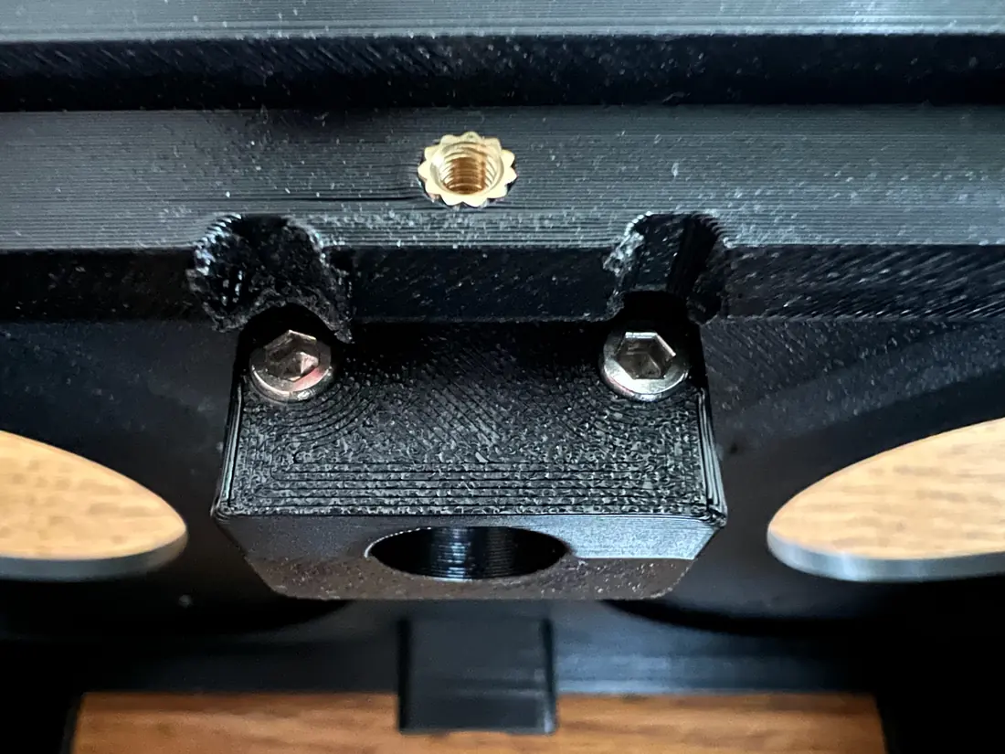
From printing to designing.
A belt tensioner made for this robot. By July, the project was drawing its own parts.
An open quadruped robot
Meet Szarik. A robot to build, understand
and discover the world with.
A hands-on project in development. Build cost and time are still being established.
For curious makers comfortable learning mechanics, electronics and code.
Small robot. Big learning curve.
If you can write software but have never made a motor move, this is a place to start. Szarik connects printed parts, electronics and code in one project you can take apart.
The hero is a rendered motion and conversation demo. Physical performance remains work in progress.
From the workbench
Before the renders came copper wire, printed parts and plenty of things that didn’t fit. A few moments from the build diary.
A belt tensioner made for this robot. By July, the project was drawing its own parts.
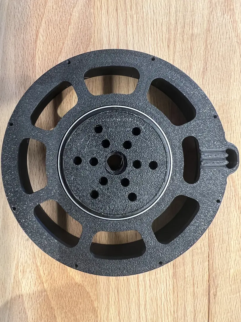
Consistent resistance readings—and a rotor that still rubbed slightly. The difficult bits are part of the story.
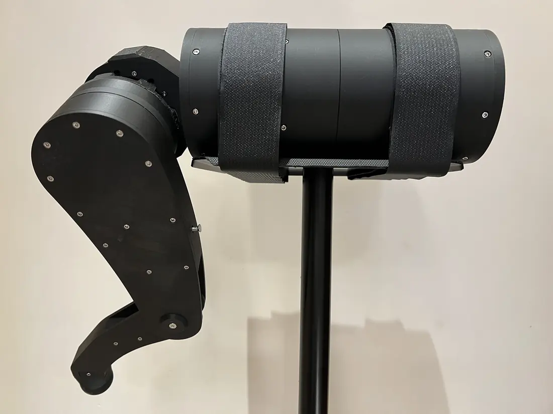
On a stand, with the feet clear of the floor. A way to learn one joint at a time.
Inside every joint
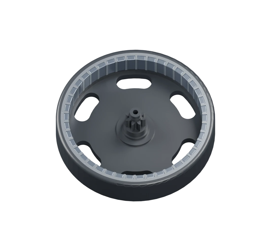
Twelve actuators make the robot move. Start with one: a magnetic motor, a planetary gearbox and parts you can print yourself.
The Szarik actuator
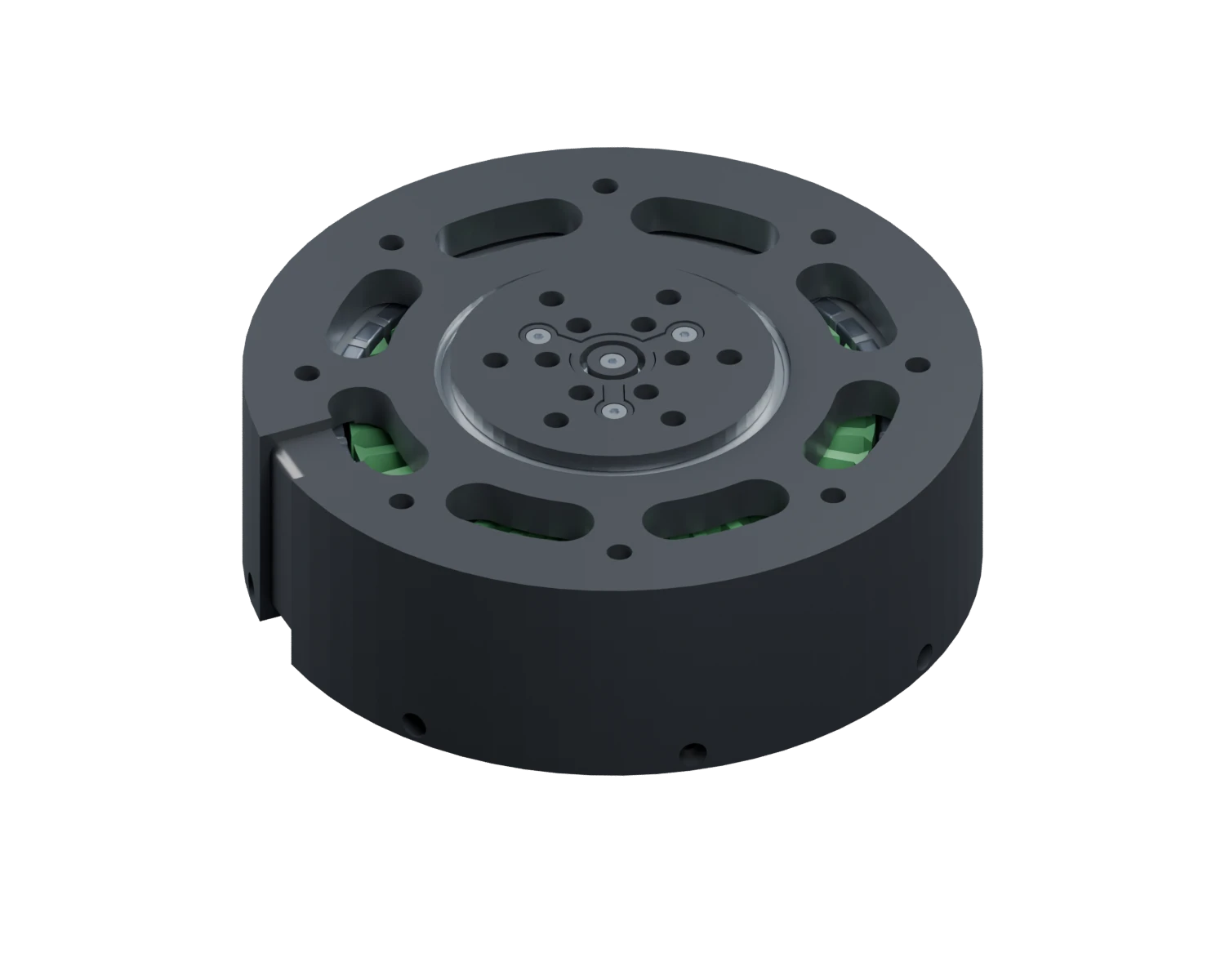
Printed mechanics. Real metal hardware.
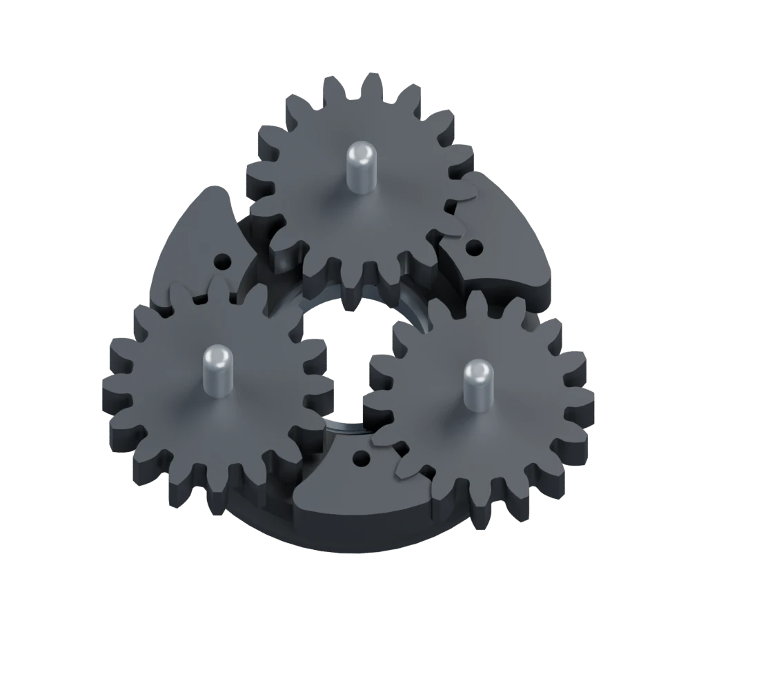
Six motor turns.
One output turn.
 42
Alternating north and south.
A shared job
The planet gears travel around the sun gear, inside a fixed ring.
For one actuator in the current print release. Purchased hardware is additional.
Housing, backplate, rotor, output, rotor cap, outer bearing retainer, back cover, planet carrier, stator lock, bearing retaining ring and three planet gears. The optional manual handle is separate.
Purchased hardware includes magnets, bearings, pins and fasteners. A complete hardware-inclusive count for this revision is still being verified.
Estimated printing time for one actuator, across four plates.
Current print release 909: Bambu Lab H2S, 0.4 mm nozzle and saved PETG Basic profiles. Four plates total 14 h 34 min 1 s. Assembly, post-print cooling, support removal and reprints take additional time.
PETG for the printed parts and supports in the current sliced package.
The four plates use an estimated 158.46 g, 71.62 g, 23.88 g and 6.21 g: 260.17 g in total. This includes supports and is material consumption, not assembled actuator weight. Complete actuator weight still needs a scale measurement.
From the outside in
A simplified CAD view of the assembled actuator.
Design facts, not rated performance. Torque, efficiency and thermal limits still need measurement. Explore the leg →
From a joint to a step
Three actuators work together to place a foot. A toothed belt carries the knee drive down the thigh, keeping its motor close to the hip.
The Szarik leg
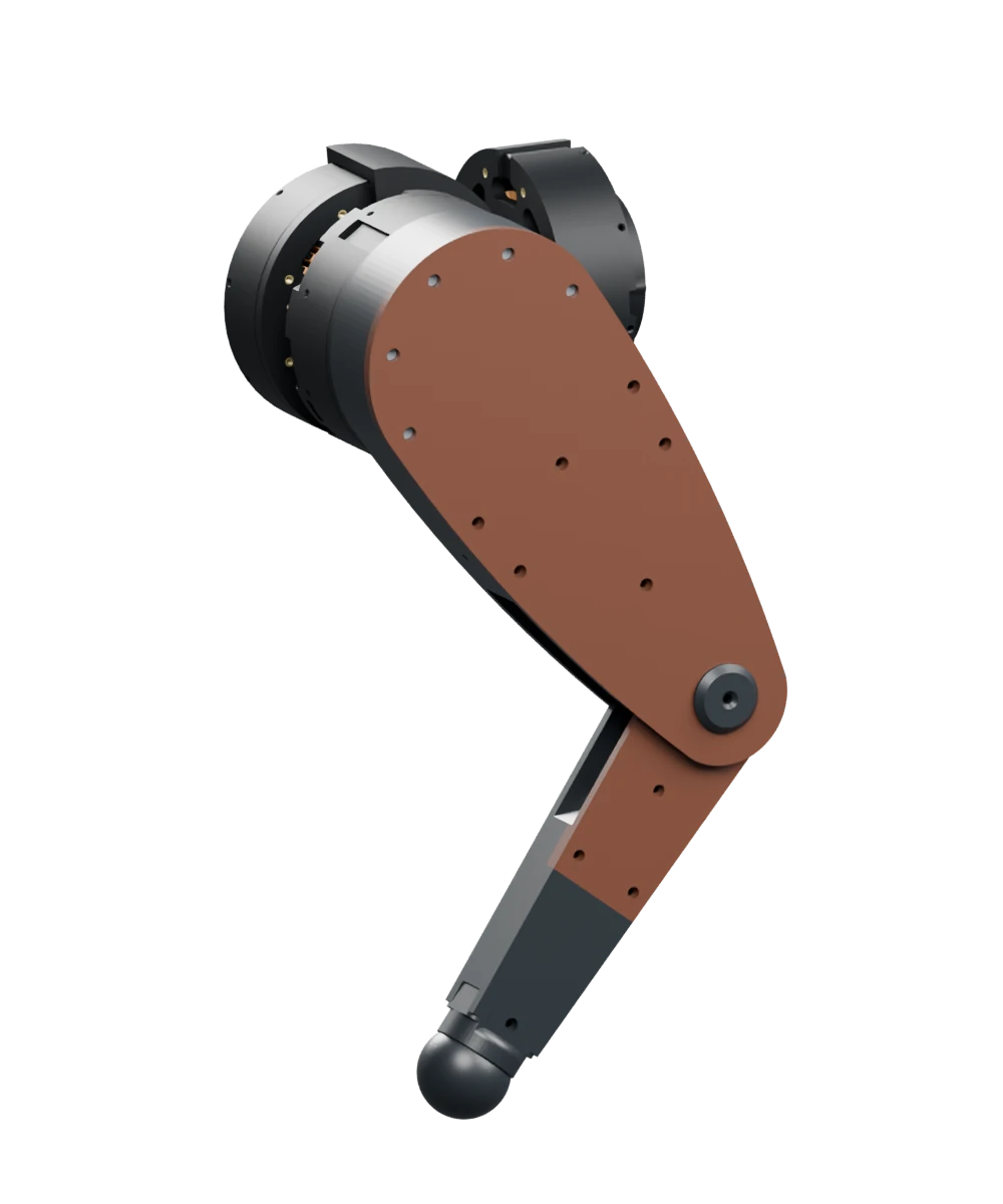
A CAD view of the complete leg.
Hip roll moves sideways.
Hip pitch swings the thigh.
The knee folds the lower leg.
The belt adds another reduction between the knee actuator and the lower leg.
A motor at the hip. Motion at the knee.
The smaller pulley drives the larger one: 28 ÷ 18 = 1.56. The lower leg turns more slowly, with greater ideal turning force. Belt tension, friction and flex affect what reaches the foot.
9.33:1 rotor-to-knee reduction6:1 planetary × 28:18 belt · ideal kinematic ratio
Room to move
Reference software ranges
Physical travel remains unverified.
Hip roll
±46°Side to side.
Hip pitch
±120°Thigh forwards and backwards.
Knee
±149°The model permits bending both ways.
Angles are relative to each joint’s model zero and rounded to the nearest degree: hip roll ±0.8 rad, hip pitch ±2.1 rad and knee ±2.6 rad. The tracks compare those configured spans on a common 360° scale. These are software bounds, not measured mechanical stops or a guarantee that every combination is collision-free. Physical clearance, cable routing and usable travel need validation on the assembled robot.
CAD geometry and software configuration. Belt efficiency, usable travel and load capacity still need physical measurements.
Everything comes together
The body connects four legs, carries the computer and gives the battery its own compartment. Printed parts make the structure something you can build, open and understand.
The Szarik body
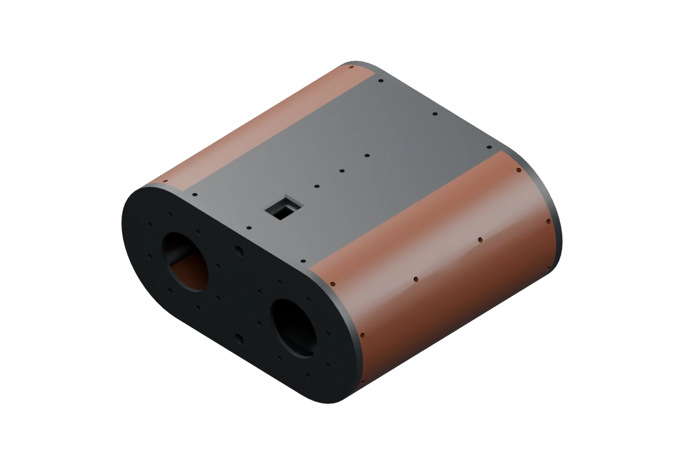
Reference CAD structure. Internal installation evolves as the robot is built.
Mounting plates join the legs to a body built from printed panels and carbon-fibre tubes.
Removable covers give access to the hardware. Threaded inserts let printed parts meet metal fasteners.
A place for the essentials
The documented electronics layout keeps the Raspberry Pi horizontal on its tray, with the power HAT above it. The Bosch pack uses a printed battery box, rails and contact carrier. CAD packaging is a reference; connector mating and final installed clearances still need physical checks.
A face for physical AI
Two cameras, a microphone array and a speaker share a head with a little personality. Black and brown printed parts give Szarik his German Shepherd look.
The Szarik head
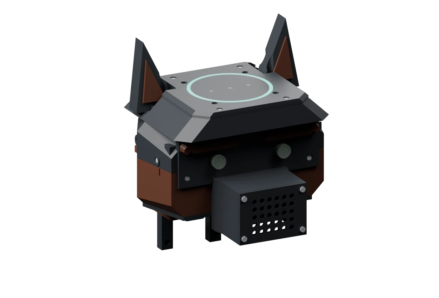
Separate brown eyebrows. A narrow halo. A printed home for cameras and audio.
ArduCam B0179 camera modules. Stereo experiments compare their views to estimate distance.
Nominal camera spacing in the rigid CAD carrier. Accurate depth depends on calibration of the actual camera pair.
Vision · 2 × IMX219
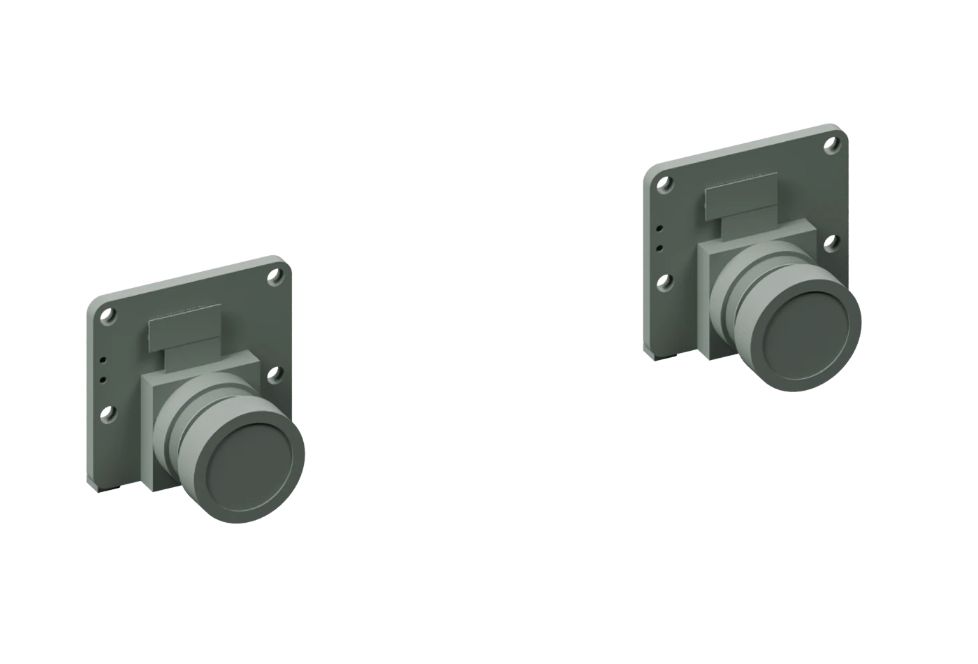 8MP
Two off-the-shelf camera modules give the computer two views of the same scene. Comparing their images is the starting point for stereo depth.
ArduCam lists the B0179 family at US$19.99 per module, checked 6 November 2026, before shipping and tax. This is a reference listing, not our recorded purchase price. The physical boards are UC-609 Rev.E; cable compatibility is revision-specific.
Camera listing ↗Hearing · ReSpeaker XVF3800
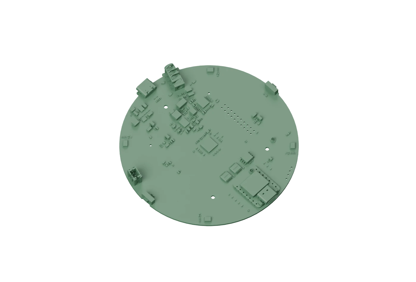 4
Four microphones feed the XMOS XVF3800 audio processor. The selected module includes XIAO ESP32S3 and connects to the Raspberry Pi.
The manufacturer provides beamforming, noise suppression and acoustic echo cancellation. Beamforming combines the microphones to favour a direction. Echo cancellation helps reduce the speaker’s own sound in the microphone signal. Results depend on the room, enclosure and setup.
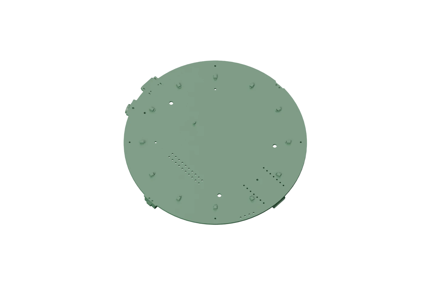 ReSpeaker hardware ↗
Voice · Seeed 114993346
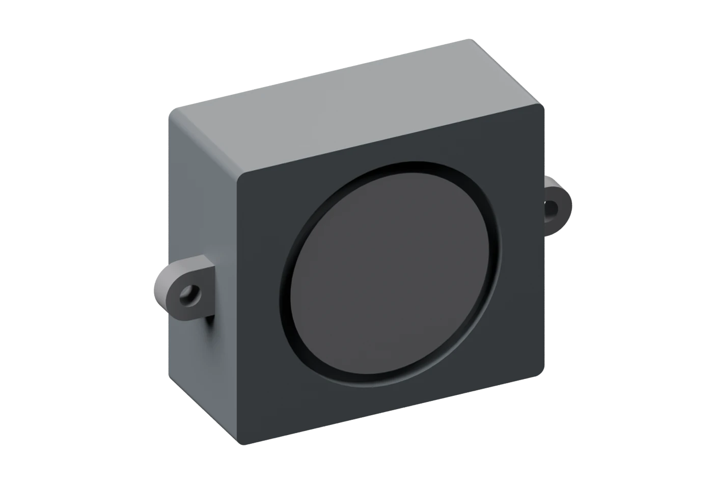 5W
A separate enclosed speaker plays Szarik’s reply. The selected Seeed unit is rated 5 W with a 4 Ω impedance; that is a component rating, not a measured audio output.
ReSpeaker handles the microphone signal and audio interface; the speaker turns the output into sound. This speaker has worked electrically with ReSpeaker. Mounting, enclosure acoustics and vibration still need physical checks. The hero conversation is recorded.
Speaker specification ↗Why two cameras?
A real stereo experiment
from the Szarik project.
Hold a finger in front of you and close each eye in turn. It seems to move against the background. Stereo vision uses the same effect: find the same feature in both images, measure its shift, then estimate its distance using the camera spacing and calibration.
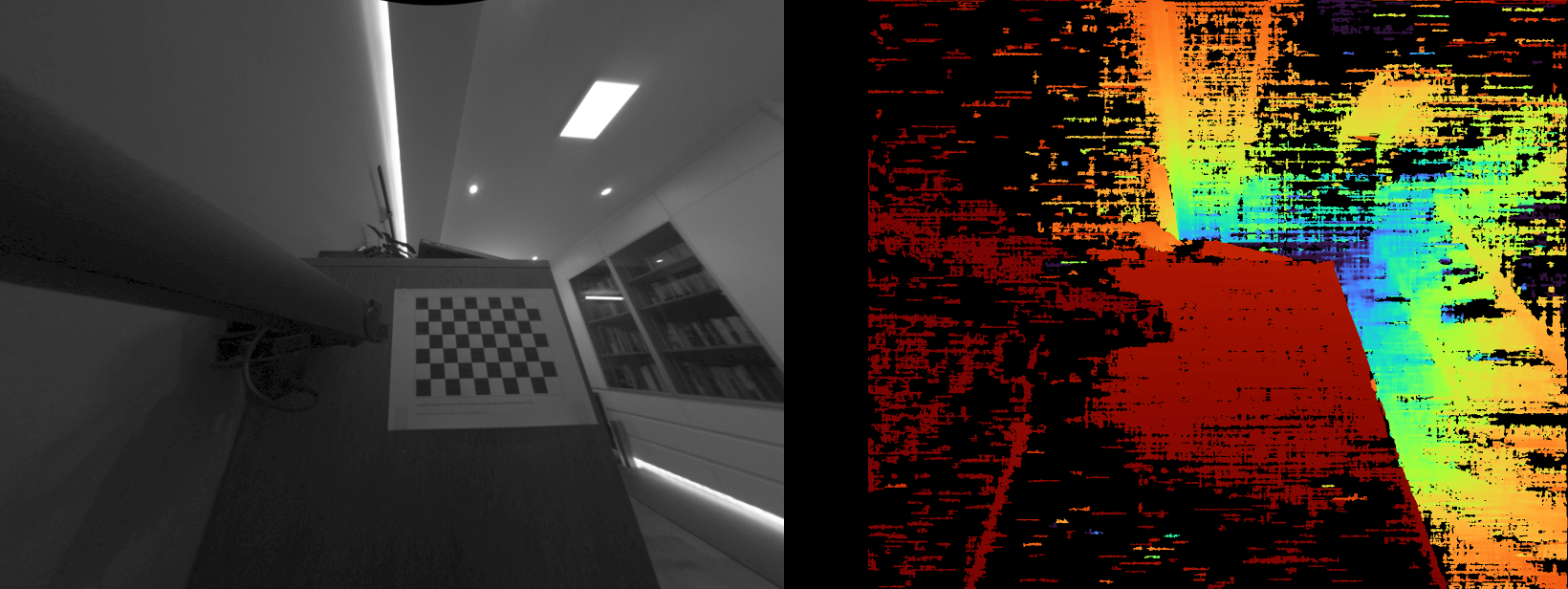
An early experimental result. Gaps and noisy edges show where the estimate is uncertain; black does not mean clear space.
These are the aligned left and right views from the same experiment. Horizontal guide lines help check that corresponding features lie on the same rows. Their horizontal shift is called disparity. Nearer features generally shift more; farther features shift less.
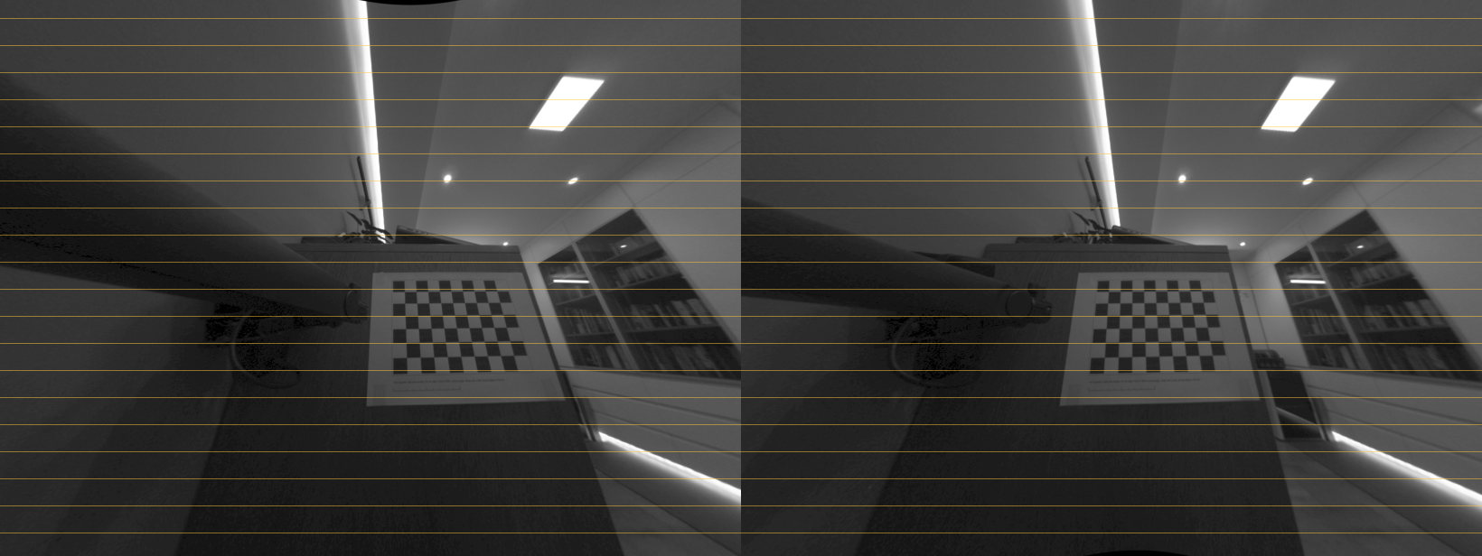
Calibration, lens distortion, scene texture and timing all affect the answer. This image is a development result, not a claim of rated ranging accuracy.
A little attention
The selected narrow halo is a visual way to express attention. The rendered demo illustrates this interaction; hardware behaviour is still being developed.
The signal behind the movement
A central computer works with a small dispatcher and a driver at every joint. Each board has a clear job.
Raspberry Pi 5
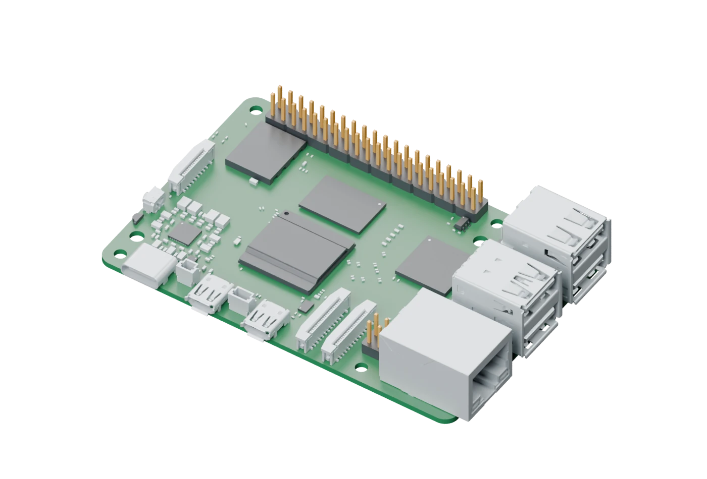
Robot-side software, control calculations, recordings and camera experiments.
One ERAD 2.1 board per joint. Each handles its motor and local rotor-angle sensing.
The AS5048A encoder reports 16,384 positions per rotor turn. Resolution is not a promise of joint accuracy.
Runs the robot-side application and calculates movement.
USB → spineSupervises and distributes joint commands.
ESP-NOW → joint driversTurns commands into three-phase motor drive, using local feedback.
One board per actuatorFrom the battery to every joint
A Bosch ProCORE18V pack sits in the printed battery compartment. The power design links that pack to the computer and twelve joint drivers.
mjbots mjpower-ss
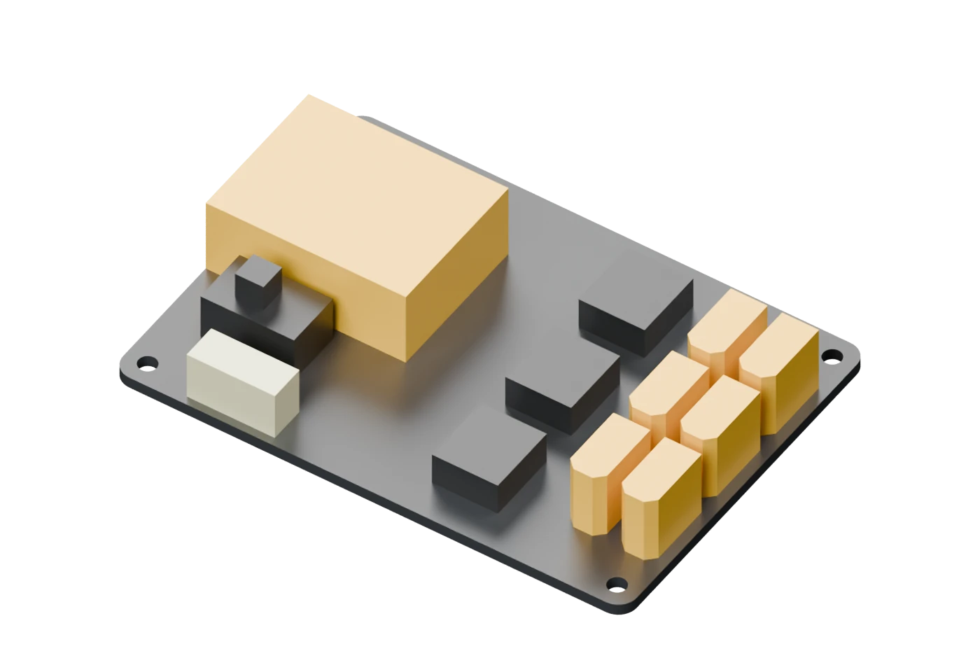
Pre-charge and six switched outputs. Pre-charge fills the drivers’ input capacitors gradually, reducing the initial current surge.
Bosch ProCORE18V 4.0Ah.
The pack shown in the project’s photographs and CAD.
18 V nominal × 4 Ah.
Runtime depends on movement, load and the usable battery capacity; it has not been measured.
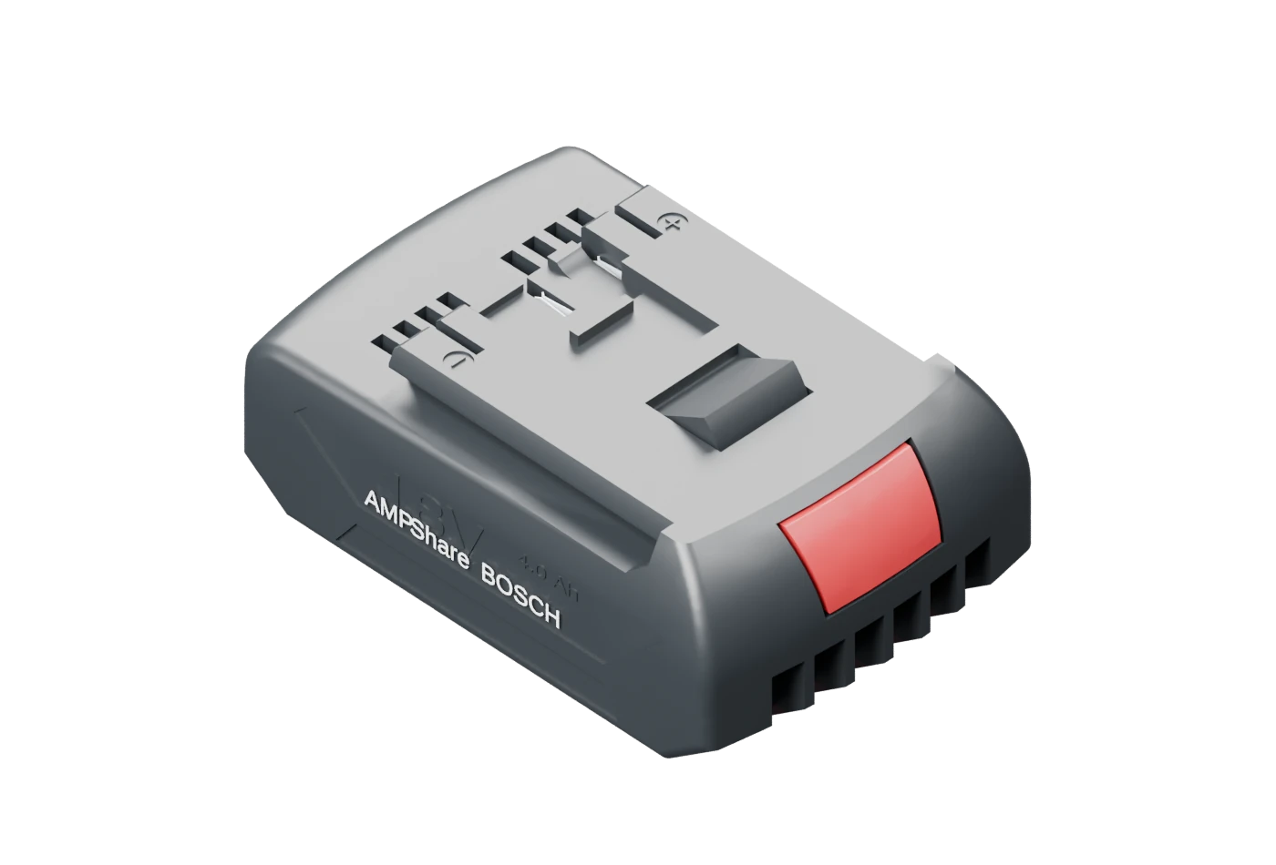
A familiar pack. A custom home.
The removable tool battery fits into the robot’s printed compartment and adapter system. The pack illustration follows the photographed ProCORE model; rail and contact geometry still need physical verification.
The power path · proposed harness architecture
Printed compartment and adapter. Protection and service-disconnect details still need qualification.
The mjpower-ss pre-charges and distributes the motor supply. A separate regulated logic branch is proposed for the Pi.
Proposed grouped power feeds, with local drops to each joint driver. Cable sizes and protection depend on measured demand.
Each ERAD converts its DC supply into the motor’s U, V and W phase connections. Those are different from the battery pair.
Two jobs, two power levels
The KAmodRPI5 REL+POW HAT supplies the Pi through its header at 5.1 V, with a published 3 A continuous rating. The HAT’s small relays are not the motor power switch. Final fusing, cutoff wiring, current limits and thermal performance remain engineering work to verify.
Make something you can understand
A robot brings the whole stack together. Follow one question from the workbench all the way to the code.
Printed housings and gears meet bearings, magnets, copper and fasteners. Learn why a part that looks right in CAD can still need another print.
Explore the actuator →Each joint has its own ERAD 2.1 driver and magnetic encoder. A spine board joins the twelve joints to the Raspberry Pi.
See the architecture →Rust handles the core control logic. Python drives experiments and simulation. The operator console makes the state visible.
Meet the software →See what the software sees
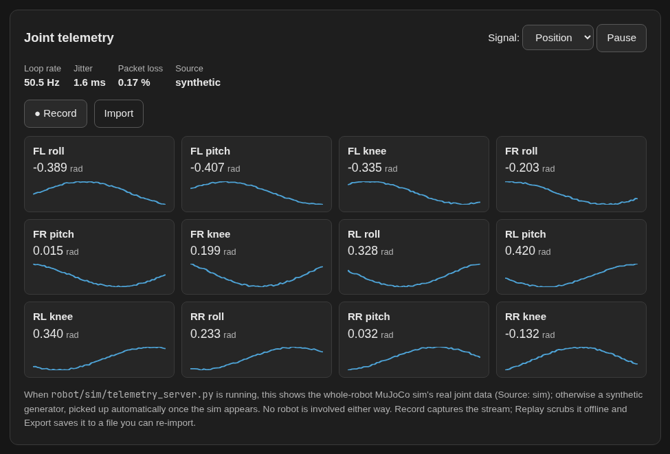
The operator console shows the robot’s state, telemetry and configuration. It’s one more way to turn “why did it do that?” into something you can investigate.
Screenshots from the project’s operator console. This website does not connect to or control a robot.
The open toolbox
From a sketch to a printed part, from a circuit to a line of code. Open source tools make the process something you can inspect, adapt and learn from.
The language
Core control logic and shared software, with checks that catch many mistakes before the code runs.
The editor
A keyboard-driven place to write code, understand changes and keep learning.
The foundation
The Linux foundation of the development desktop. A system you can understand and shape.
BTW, we use Arch, Neovim, and Rust.
Mechanical design
Parametric parts and assemblies. Dimensions, interfaces and the geometry behind the printed robot.
Electronic design
Schematics, circuit-board layouts and 3D inspection. Follow a signal beyond the software.
Interface design
An open design and prototyping tool for exploring interfaces before they become code.
Renders & animation
Lighting, cameras and explanatory films that help show how the mechanics fit together.
Experiments & vision
Camera experiments, simulation scripts and the glue between an idea and a repeatable experiment.
Physics simulation
A place to explore robot motion and contact before comparing a model with the physical machine.
The development desktop
An Arch-based Linux desktop for the workbench computer. A considered starting point, with room to make the environment your own.
Linux, at the workbench.Curiosity, encouraged
No robotics background required to start reading. Bring your programming experience—and a willingness to meet a few new ideas.
A gearbox trades rotational speed for turning force, called torque. Here, the motor turns six times for one output turn. The three planet gears share the load as they travel around the central sun gear, inside the fixed ring.
An encoder reads the rotor’s angle. This actuator uses a 14-bit magnetic sensor: 16,384 counts across a full turn. That describes resolution—how finely it reports position—not a guarantee of accuracy under load.
Simulation lets you try control ideas against a model before working with a physical machine. Szarik uses MuJoCo. A useful simulated motion is a starting point; contact, friction and real mechanical tolerances still have to be checked on hardware.
Work in progress · 5 November 2026
The complete build cost and repeatable build time are still open. Actuator performance needs bench measurements. The hero shows a scripted rendered demonstration, not recorded physical walking or live recognition.